Probing For Answers
So, your scope is developing intermittent problems. If you’ve had the scope for a while, and the readings depend on how you hold the probe, the most likely cause of the fault is the probe itself. For example, you hold the probe just right and the reading is perfect, but turn it too sharply, and you lose the signal. Either way, once you see the signal change as you change the angle of the probe, you begin to question the accuracy of all your readings.
At this point, it is time to buy new probes. The purchase tends to be delayed, but the quality of your scope is only as good as the quality of the probes. The same is true if you are looking for probes for a new scope that comes without them. The actual probe choice will depend very strongly on what you use them for, but users need not be locked into buying expensive probes offered by the original oscilloscope manufacturer. High quality probes are available from vendors like Pomona at low cost. These can do the job equally well as the originals.
The great number of applications in the electronics industry (along with the great number of oscilloscope types) helps explain the many types of probes. Companies like Pomona sell probes that are matched to particular models, but for accurate measurements (particularly on non-mainstream scopes), it is important to understand a probe’s specifications. Most important are a knowledge of input capacitance and circuit loading, bandwidth and frequency response, and noise behavior. Finally, when parameters other than voltages need to be measured, probes other than voltage probes may come into play – some examples of this are given as well.
The ideal probe
Probes have four essential requirements. They must be easy to connect to the circuit in front of you, must not load the signal source, must pass on the signal accurately, and must be immune to noise . In practice, there will always be some loading because the oscilloscope needs to draw some sensing current. There will always be some distortion because of stray capacitances and inductances, and there will always be some noise1.
These effects can be minimized by using standard probe sets, keeping cable lengths short, and using the correct-sized probes and the correct adapter to the device under test.
Ideally, a probe would have infinite input resistance, zero input capacitance, and infinite noise rejection. Compromises among these ideal requirements and probe costs have led to three broad probe categories: general purpose passive probes, active probes for high-frequency measurements, and differential probes to eliminate undesired common mode signals. These three major categories are discussed in this article..
General purpose probes
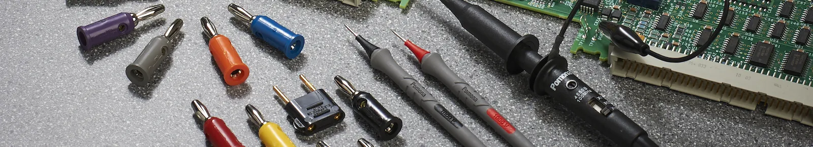
General-purpose, passive 1:1 probes (also called x1 probes, Figure 1) were first and foremost designed to fulfill the basic demand for an easy connection of a circuit under test to the oscilloscope input. Initially these consisted of little more than a shielded testlead with an ergonomically designed circuit browser or a set of small alligator clips to make the connection to the circuit-under-test.
Figure 1: Technical probe specifications for Pomona’s general purpose passive probes, showing the major probe parameters.
Figure 2
A complete probe set includes probe handle, insulating adjusting tool, sprung hook, BNC adapter, 23-cm ground lead, 25-mm ground adapter, IC tip adapter, tip cover, rigid tip and spring-loaded tip.
These probes (Figure 2) gives a 1:1extension of the oscilloscope’s input channel and the voltage-under-test is directly applied to the oscilloscope’s input. At the probe tip of a 1:1 probe, we see the input resistance of the connected instrument. The drawback of this type of probe is that not only the input resistance is seen at the probe tip, but in parallel to this we see the full cable capacitance as well as the original input capacitance of the oscilloscope used.
If the test frequency is increased, this results in a higher circuit loading. In practical designs, the 1:1 probe has some series resistance built-in in order to reduce ringing, and this together with the circuit’s output impedance reduce the useful bandwidth of 1:1 probes to no more than a few megahertz. When working with a 1:1 probe, the user has to realize that some 50 to 150 pF is loading his circuitry. Not all circuitry will continue to function properly once this load impedance is connected.
Reducing circuit loading
In order to reduce the effects of circuit loading due to the large probe tip capacitance, probes are generally built as so-called 10:1 probes which present only about a tenth of the probe cable capacitance at the probe tip. For that purpose, a voltage divider is added at the probe tip. This divider ‘masks’ the cable capacitance by about the same factor as the voltage division ratio. So a 10:1 voltage attenuation gives almost 10 times lower probe tip capacitance, using the same cable and oscilloscope input. This then allows for a much wider useful bandwidth and results in much lower circuit loading. An additional benefit is that these 10:1 probes allow for adjustments and corrections by slightly manipulating the exact values of the components used, resulting in a wide bandwidth and flat frequency response.
The effect and actual voltage division of the divider network also depend on the input impedance of the oscilloscope the probe is connected to. In general, oscilloscopes are built to present a 1 megohm input resistance, and a parallel capacitance of 10 to 25 pF is unavoidable. Probes are then designed to work with this impedance, and provide a 10:1 attenuation ratio.
Switching between attenuation factors
Below 1 MHz, it is the probe’s input resistance that determines the circuit loading. Above that, the input capacitance begins to take over. Switching between attenuation factors also changes the input resistance and capacitance and hence the bandwidth and associated rise time. A 10:1 or 100:1 probe will compensate for a scope’s input capacitance range to give a flat frequency/attenuation ratio.
Probe reactance affects system bandwidth
The reactance of a probe is the major contributing factor in determining the bandwidth (maximum –3dB frequency) of the scope/probe system. The bandwidth is then defined as the highest frequency that can be displayed with an amplitude that is no more than 3 dB lower than the actual signal amplitude is. Verification is done by comparing high frequency response to low frequency response.
Scope manufacturers indicate the ‘useful system) bandwidth’. This is the bandwidth of the oscilloscope that the probe can be used with without reducing the overall system bandwidth. A scope probe that is offered for use with a 100 MHz scope should again result in a system bandwidth of 100 MHz. Seldom do you find the probe only bandwidth, as there is hardly a way to determine it and no way to benefit from it. Probes should match or exceed the scope’s bandwidth - if a probe would have a probe-only bandwidth of say a 100 MHz and would be used on a 100 MHz scope, the amplitude on screen will be 3 dB down at the rated frequency. And this 3 dB equals an amplitude reduction (error) of about 30%! If this sounds like a large error to you, remember that most scopes have a DC accuracy of 2 to 3%, sometimes more. At frequencies beyond a few kilohertz, the effects of frequency-roll off start coming into play, and at the specified bandwidth the amplitude response is down by 3 dB. At even one quarter of the bandwidth this can easily lead to amplitude errors like 10%.
Measuring risetimes
The bandwidth has a corresponding pulse risetime (the time to respond to an instantaneous pulse). When the user wants to measure a signal’s risetime he needs to use an oscilloscope plus probe combination that has a bandwidth sufficiently wide to cope with the highest frequency components contained in the signal. Hence, the risetime of scope plus probe needs to be significantly shorter than that of the signal under study. If not, the scope plus probe will dominate the measurement, and not the signal under study. The rise time of scope plus probes should be less than a quarter of that of the signal waveform for the resulting risetime on the scope screen to be within about 3%.
Input capacitance is more important than resistance in pulse risetime measurements, while the resistance is more important in pulse amplitude measurements. As a general rule of thumb, pick a probe with the highest overall input impedance (highest input resistance and lowest input capacitance) for the lowest circuit loading effect. Since fast risetime is closely related to high bandwidth, pick a probe with the lowest capacitance for best results. If multiple testpoints are available that carry the same signal, choose the point that has the lowest circuit impedance, because there the signal will least be affected by the probe being connected. Pomona probes are designed to give a full, accurate voltage read-out throughout the entire rated probe bandwidth. These probes include such important features as low input capacitance and high bandwidth to meet the high-performance demands of today’s oscilloscopes.
Each scope has its own input resistance and input capacitance, and careful probe design is needed to avoid influencing a scope’s response. Cable lengths should be kept short to prevent capacitive loading.
Reading voltages with attenuating probes
Apart from the low complexity of the 1:1 probe, another advantage is that the measured voltage seen on the oscilloscope is in fact the actual voltage at the probe tip. This is not the case with 10:1 and 100:1 probes, and in order to read the actual voltage at the probe tip from the measurement on the oscilloscope screen, the user has to take the probe’s attenuation into account, so multiply any amplitude measurement result with 10 or 100. Some scopes can sense the probe attenuation factor and account for this to show the correct vertical (V/div) sensitivity settings on screen. Some others have a possibility to manually set this probe type and have the oscilloscope adopt its reading and/or measurement results.
Thanks to the probe recognition system the oscilloscope can work with an attenuator setting of say 10 mV/div, and indicate the overall vertical sensitivity as 100 mV/div thereby taking into account the effect of the 10:1 probe. The result is that the amplitude measurements are correct and do reflect the actual voltage at the probe tip. This also requires a readout actuator on the probe to communicate the probe attenuation factor to the scope. Probes with readout actuators are available from vendors like Pomona.
Multi-channel measurements
In many cases an oscilloscope is used to make signal comparisons, e.g. input signal versus output signal of an amplifier system, logic system, etc. Some applications require the analysis of even more signals, hence four channel oscilloscopes are wide spread. For such multiple-channel measurements in particular, it is important to make sure that both (or all) probes have the same characteristics: the same bandwidth and risetime, the same frequency characteristics. When timing measurements are made in the nanoseconds range, it is also important to ensure that all probes have the same physical cable length. As a signal travels through a coaxial cable at a speed of 5 ns per meter or slower, a difference in cable length may easily result in timing errors in the nanoseconds range. For this reason it is best to replace a defective probe by another one of the same type, or alternatively to replace multiple probes at the same time.
Active probes for high-frequency measurements
Attenuating resistors in the passive probe increase the input impedance, but at the expense of signal strength. Active probes use devices like FETs (field effect transistors) to increase the input impedance and reduce input capacitance below 1 pF without losing signal strength. Active probes are therefore needed for very high-impedance circuits to avoid overloading them, and for extremely high frequency measurements into the GHz range.
At frequencies like hundreds of megahertz, the bandwidth limitations of passive probes form a practical limitation, because the probe tip capacitance forms too low an impedance and truly disrupts the proper functioning of the circuitry under test. As circuitry running at these frequencies is usually laid out using transmission-line interconnections (e.g. 50 or 75 ohms coaxial lines), probes with 500 ohms resistive impedance are used here, that are connected to 50 ohms cables and 50 ohms coaxial oscilloscope inputs, thereby giving a 10:1 voltage division. Such probes are generally referred to as ’50 ohm probes’. Other resistance values are used as well, giving 20:1 or even 50:1 voltage division ratios.
Ground connections
Essentially, any voltage probe measures the voltage between the probe’s center tip and the ground contact. Too long a ground lead will add inductance to this signal path, which may cause ringing on the waveforms measured. Some users rely on the safety ground for the probe to find its reference potential. By doing so, large measurement errors are easily created, especially in the medium and higher frequencies. Additional ringing may result from the long wiring, and stray voltages may influence the measurement due to other currents flowing through the overall wiring.
Always use a ground- or reference contact on each individual probe and make sure this is as short as possible. Don’t extend the ground leads supplied with the probes in any way.Most probe manufacturers deliver a dedicated spring-loaded ground contact with high frequency probes, that is no longer than ½ inch and that is meant for critical measurements in the higher frequency ranges.
At high frequencies, a lead’s distributed inductance and capacitance may also need to be considered. Ground paths particularly should be short to minimize the series inductance which, with the probe capacitance, causes ringing at specific frequencies. Probe manufacturers reduce these effects by selecting the inductance to raise the ringing frequency above the scope/probe bandwidth. Leads should hence be extended only carefully. Although it is convenient to extend probe leads when checking large boards, this can cause ringing on step changes in input.
Probes should be shielded to make them (relatively) immune to noise sources. FET probes generally have a 50 ohms output impedance for driving 50 ohms cables, which increases the permissible length of coax cable. Their low maximum input voltage of usually only a few volts limits the application of active probes to measurements on fast semiconductor circuits.
Differential probes for low noise applications
Figure 3
The signals measured by differential probes are subtracted by a differential ampllifier, improving sensitivity to small signal differences.
Differential signals, also identified as ‘symmetrical signals’ (in phone, power and disk read circuits, for example) need differential probes. Although all measurements are differential in the sense that they measure the voltage difference between two points, a differential probe (Figure 3) measures two signals that may both be above ground. The signals are subtracted by a differential amplifier, which helps improve sensitivity for low amplitude signals (which particularly can be plagued by noise and lack of sensitivity). The differential amplifier is greatly insensitive to common mode signals, that is signals that have the same amplitude and phase and that are applied to both inputs, such as those resulting from crosstalk and noise from adjacent circuitry.
Single-ended measurements (i.e. measurements referenced to ground or to a common), can cause amplitude and timing errors in high-speed signals. Differential probes like the Pomona differential probe are matched, to avoid delay differences between signal paths from skewing the signals. Here particularly, the two leads should be identical. Ground loops must also be minimized, and kept short. A simple way of reducing distortion from noise and line-frequency is to twist the two probe cables together.
Differential probes also give a high common-mode noise rejection and may be needed in noisy environments. Floating measurements (the term for differential measurements in power systems, because there the isolation from the lethal power voltages is a critical parameter) also often require high common mode rejection to detect the smaller voltage signals of interest. Floating measurements taken in the field should have full insulation for extra safety, and can therefore best be carried out using safety-designed portable scopes.
Probes should be designed to standards like IEC1010-2-031, with insulation for the entire probe including the BNC connector. For Pomona probes, a spring-loaded sheath covers the tip ground point, and there is a compensation point in the BNC end.
Measurements on power systems call for special precautions as the general oscilloscope is itself ground referenced, and has this power ground reference contact directly connected to the signal common or signal reference – namely the shielding of the probes and the ground contact near the probe tip. Without dedicated precautions, measurements directly on the mains power (and on any circuitry connected to it) may lead to short circuiting the mains power system to ground.
Some people try to avoid this by interrupting the ground wire in the scope’s power cord, thereby imposing the risk of death or injury due to lethal voltages being present on the oscilloscope’s common reference and front panel! The proper way to make such mains power-related measurements, is to use a safety designed scope without any common ground contacts, such as Fluke’s ScopeMeter 190 Series. If no such instrument is available, a differential probe with insulation may be used to keep the lethal mains voltages away from the scope input and from the ground contact, still providing the necessary measurement capability.
Adapting to fine-pitch ICs and surface mount devices
It should be easy to connect the probe to a test point, since probing a difficult connection can give inaccurate readings. Needle type probe tips are fine when the probe just needs to be touched to the test point to make a connection. Retractable hook tips are easier for leaving the probe attached and making adjustments. Manufacturers like Pomona provide probes with special tips for fine-pitch ICs and other test points that are hard to reach. Many Pomona scope probes also offer a spring-loaded pogo pin as the main contact pin. This offers advantages to the end user like a steadier contact to the test point, replaceability of the probe tip, and choice of pin tips.
Surface mounting circuits also need specialized connectors. The Pomona Micro SMD Grabber test clips shown in Figure 4, for example, clip to the tip of the oscilloscope probe (Figure 5). Ground and tip leads are short for minimum noise (Figure 6), and the clips can be used with PQFP packages with 0.3 to 0.5 mm lead pitches. A thin body design allows an unlimited number of clips to be stacked side by side. Corresponding long-tipped probes work with 0.5 mm lead pitches or greater, also maintaining 100 MHz maximum
frequencies.
For the miniaturized contacts of surface mount components, the first of a probes’ four basic requirements (easy connection to the circuit in front of you) is particularly clear. Meeting the other three requirements (input impedance high enough to avoid loading, accurate signal relay, and noise immunity) can involve
complicated calculations. High-quality and experienced probe suppliers like Pomona (which has been building electronic probes and connectors for 50 years) make the work much, much easier.
Figure 4
Figure 5
Micro SMD Grabber test clips have a very thin body, and stack side by side for PQFP, SOIC, TSOP and SSOP packages.
Probe tip adapters connect Micro SMD Grabber test clips to the oscilloscope.
Figure 6
Micro SMD Grabber test clips have short ground, and tip leads are short for minimum noise.
Other probe types
While standard oscilloscope probes measure only voltage, current probes measure current, usually by means of a current transformer. Conventional AC-only current probes use a transformer to convert current flux into a voltage to be presented to the oscilloscope input. Frequency responses are from a few hertz up to some gigahertz. Adding a Hall-effect device reduces the frequency response down to DC, but also limits the maximum frequency to around 50 MHz.
Current probes can be used next to voltage probes to read both voltage and current at the same time and measure both parameters as a function of time simultaneously. From this, the most advanced oscilloscopes can calculate power waveforms, representing power as a function of time, so as to determine the instantaneous power handled by, for instance, power FETs or linear amplifier stages. As with voltage probes, current probes must not overload the circuit, and must have an appropriate bandwidth and rise time.
High-voltage probes use higher attenuations (x100 and higher), and have lower input capacitance (about 3 pF typically). Here and elsewhere, high-voltage safety limits for probes should never be exceeded, this is particularly true of the maximum input voltage, which will usually be derated with frequency. Make sure you are aware of how maximum allowed voltages diminish with frequency for the particular probe you’re using. Furthermore, safety measures need to be kept in mind even more strictly when working with high voltages than in low voltage application, as mistakes may have permanent consequences to the probe user….
The international standard EN61010-2-031was written specifically to provide probe manufacturers with design rules that ensure safety of the probe construction, and thus assure the safety of the technician applying these probes. When selecting a probe, make sure that it is specified according this standard and use it according the instructions provided by the probe manufacturer, so as to secure your own personal safety!
Conclusion
In essence, when looking for replacement general-purpose scope probes, look for accuracy, versatility, and value. Make sure that the probe you’re considering meets the safety requirement for the application you have in mind, and don’t use the probes beyond the specified voltages. Fine tip probes are needed to explore high-density chip leads with less than 0.060-inch (1.5 mm) spacing. Modular probe handles are useful to receive a variety of spring loaded and fixed tips, for greater testing versatility.
About the author:
Dwight Hyland is Product Manager for Pomona Electronics. During his twenty years in the electronics industry, Hyland has served in a number of capacities including product specialist, product planning, and product development management until assuming product management responsibilities for the electronic product line.