-
-
A message to our customers, partners and distributors about COVID-19
Read now
-
Check out what's new
2019-2020 New Product Brochure
Learn more
-
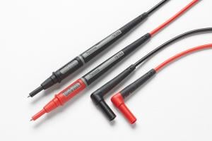
When accuracy is critical
Reliability and value
Read now
-
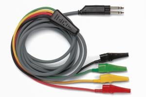
Simplify your choices
5674C Deluxe Electronic DMM Test Lead Kit
Learn more
-
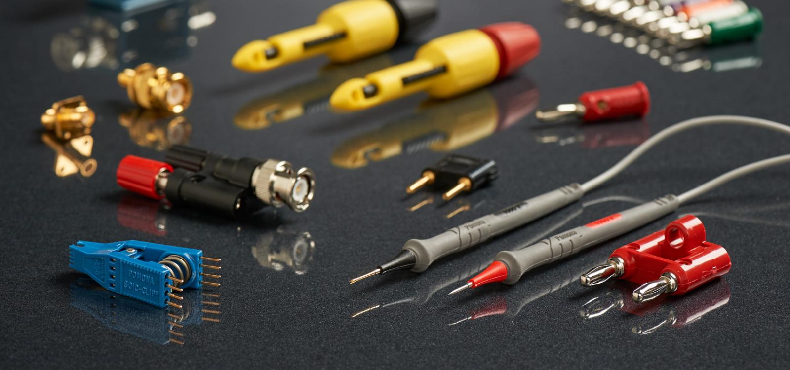
Connecting with quality
RF Coaxial Connectors, Adapters and Kits
Learn more